MAX31865 module
PT100 and PT1000 platinum sensors are Resistance Temperature Detectors (RTD). As a result of the change in temperature, a change in resistance occurs. To measure the resistance of sensor a special circuit needed. This is what MAX31865 module does. MAX31865 module is a RTD to Digital converter module for PT100 and PT1000 sensors. The module makes it easy to connect platinum sensors to Microcontroller based applications or card size computers like Raspberry PI. Four pins are used for SPI compatible communications.
MAX31865 module 3.3V


×
Click on the image to enlarge it.
MAX31865 module 5V


×
Click on the image to enlarge it.
5V variant comes with level shifters to interface with 5V system. Except this difference both variant is the same.
Characteristics
- 3.3V variant:
- Supply voltage: 3.0 to 3.6V / 3.3V recommended
- I/O line voltage levels: 3.0 to 3.6V / 3.3V recommended
- 5V variant
- Supply voltage for MAX31865 chip (3V3 pin): 3.0 to 3.6V / 3.3V recommended
- Supply voltage for level shifters (5V pin): 4.5 to 5.5V / 5.0V recommended
- I/O line voltage levels: 4.5 to 5.5V / 5.0V recommended
- MAX31865 chip with 15bit ADC converter for high accuracy analog to digital conversion
- SPI interface
- Compatible with 2, 3, 4 wire sensor connection configurations
- PT100/1000 sensor NOT included
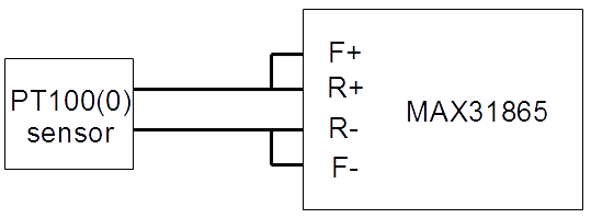
PT100 / PT1000 connection configurations
On the PCB there are short labels, their meanings are:
F+ = FORCE+
R+ = RTDIN+
R- = RTDIN-
F- = FORCE-
2 Wire connection configuration
3 Wire connection configuration

4 Wire connection configuration

Difference between MAX31865 modules for PT100 and PT1000 sensors
Both MAX31865 RTD to digital converters are assembled on the same PCB and most components are the same. Only 2 component values differ, Rref and C1
| Rref | C1 | |
| PT100 type | 400Ω | 100nF |
| PT1000 type | 4000Ω | 10nF |
Note: 4000 device marking means 400Ω resistor (400✕100)

4001 device marking means 4000Ω resistor (400✕101)

These are 0.1% precision resistors.
Solder jumper settings
There are 3 pads what functions as solder jumper settings for 2, 3 or 4 wire connection.

Solder middle and lower pad together for 2 or 4 wire connection.(like on picture above)
Solder middle and upper pad together for 3 wire connection.
Arduino Due connection diagram

Connection with Arduino Due (3.3V interface)


×
Click on the image to enlarge it.
Please note, MAX31865 works with 3.3V level signals. Do not connect directly with Arduino Uno, Mega or other 5V system. Arduino Due is a 3.3V powered device.
Connection with Arduino (5V interface)

Connection with Arduino UNO


×
Click on the image to enlarge it.
5V compatible board comes with 3.3V <=> 5V level converters. It works with Arduino Uno, Mega, Nano and other 5V compatible circuit.
Connection with Arduino Nano


×
Click on the image to enlarge it.
Arduino SPI pinout
Every Arduino board has a 6 pin ICSP connector. You may use this to connect MAX31865 board. SPI pins are only available via ICSP connector on Arduino Due.

On other Arduino boards ICSP is also available or you can use DIGITAL pins.
| Arduino Board | MOSI | MISO | SCK |
| Uno | 11 | 12 | 13 |
| Mega | 51 | 50 | 52 |
| Nano | D11 | D12 | D13 |
Connection with Teensy 3.1/3.2

How temperature measurement works?
PT100 and PT1000 are resistance temperature detectors (RTD). The resistance at 0°C is 100Ω for PT100, 1000Ω for PT1000.

The figure above shows the relation between temperature and resistance.
In MAX31865 two 8 bit registers - RTD MSB and RTD LSB - contains the RTD resistance data.
RTDdata = RTD MSB:RTD LSB
RTDdata is 16 bit wide, containing 15 bit ADC code + 1 bit fault flag which is 0th bit.
ADCcode = RTDdata>>1
Next step we calculate the actual resistance of RTD:
R = (ADCcode * Rref) / 32768
where Rref is 400 if PT100 used or 4000 if PT1000 used. (You can find this equation on 18th page in data sheet)
Now we know the actual resistance of RTD (PT100(0) sensor). There are several ways to calculate temperature from resistance.
Linearization
Temperature (°C) = (ADCcode/32)-256 formula gives quite acceptable result in -100 to 100 range. For more information please read "Linearizing temperature data" chapter on 10th page of data sheet.
Advantage: this is the simpliest temperature calculation method
Disadvantage: while graph is non-linear, out of range the accuracy will decrease.
Using table
You can download resistance tables for PT100 or PT1000. In this table find the closest resistance value. For example when R=112.00 Ohms in table you can find 112.06 value as the closest. After reading the corresponding row and column title of this field you will get 31°C as current temperature.
Advanteage: easy and accurate
Disadvantage: implementation on a tiny 8 bit microcontroller takes a lot of space, if you try to put the entire table into program memory. Note, table is filled with floating point values.
Callendar-Van Dusen equation I.
The Callandar-Van Duesen equation is an equation that describes the relationship between resistance (R) and temperature (t) of platinum resistance thermomethers (RTD).

R = actual resistance measured on RTD (PT100 or PT1000 sensor)
R0 = resistance at 0°C (100 if P100 connected, 1000 if PT1000 connected)
a = 3.90830 x 10⁻³
b = -5.77500 x 10⁻⁷
t = temperature in °C
Arrange this equation to get t

C code of the above equation:
t = (-R0*a+sqrt(R0*R0*a*a-4*R0*b*(R0-R)))/(2*R0*b);
In Arduino sample code I used Callendar-Van Dusen method.
Noisy environment
MAX31865 has built high resolution ADC converter which is sensitive for noise. The board is designed to eliminate issues caused by noise but some precautions are needed. It is highly recommended to operate the device from stable power supply or battery. Some computers USB supply can be noisy, especially if the mains has no proper ground. Some low quality computer power supply can generate noise on USB power pins. If you get permanent errors "PT100 sensor connection fault", I recommended to try it from battery powered device like Notebook computer.
2 wire PT100 connection is only acceptable if the sensor wire is short. (less than 1 meter long)
Use 3 or 4 wire connection for sensors with long cable.
Downloads
- MAX31865 IC data sheet
- Source code for Arduino Due (Arduino IDE 1.8.13 tested)
- Source code for Teensy 3.1/3.2
Last updated: 04/01/2021